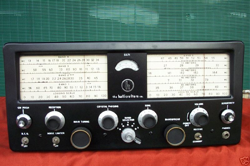
Hallicrafters SX-71 (Number 1 - Run 3)

I picked up this SX-71 for just over $100 on Ebay. The seller's photo was poor, and I knew I was taking a risk. But $100 for an SX-71 seemed like a good deal. When the receiver arrived it was in poor condition. Here follows a history of the refurbishment. I subsequently sold the refurbished unit on Ebay for $105 . The moral of this is that you shouldn't expect to make any money by refurbishing these old receivers. In fact, people seem to prefer units that are original and in poor condition, so that they can restore them, rather than already restored units.
The S-meter didn't work, and the meter needle was bent. Inspection under the chassis revealed that the meter wires were hanging loose, and unconnected. I extracted the meter, and took it apart. This is a 5ma meter, but the needle barely moved when I passed a current of 5mA through it. Closer inspection revealed that a washer had somehow been dropped between the armature and the magnet poles! Once that was removed, and the needle straightened (a very delicate operation), the meter worked fine with FSD for 5mA. Various screws inside the meter were loose, and tightened. Somebody had clearly been inside this meter before me, and botched it. That didn't bode well.
The CW Pitch control on the front panel had a modern, non-Hallicrafters knob, which was not attached properly.
Removing it revealed that the control shaft, a screw
thread, was damaged (stripped of its thread, and bent). I gently tried to
straighten the shaft, but it snapped off. I then removed the control itself from
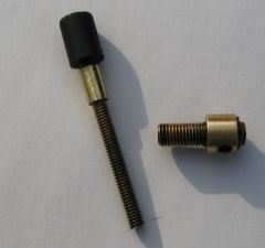
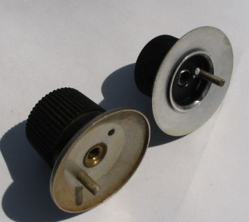
the front panel. It is a variable inductor: most unusual. Here is a photo of the
disassembled device:
To repair this, I used a brass collet and brass bolt, removed most of the existing shaft attached to the iron core, screwed the collet on, fixed it with superglue, screwed the brass bolt on, fixed that with superglue, and then cut the whole doings to the required length. Here is the result. It worked well!
I created a close replica of the CW Pitch control knob by using a knob from an old B&K frequency meter, and attaching a small stud (a length of screw thread) on the underside. This can be compared in the photo below with an original CW Pitch knob (from Jim Cain's SX-71):
Update: More recently, I found someone selling a BFO coil assembly, plus the Sensitivity and CW Pitch control knobs, so I bought those and installed them. I now have a spare, repaired BFO assembly if anyone wants one :-)
The cabinet was basically alright, although it badly
needed a paint job.
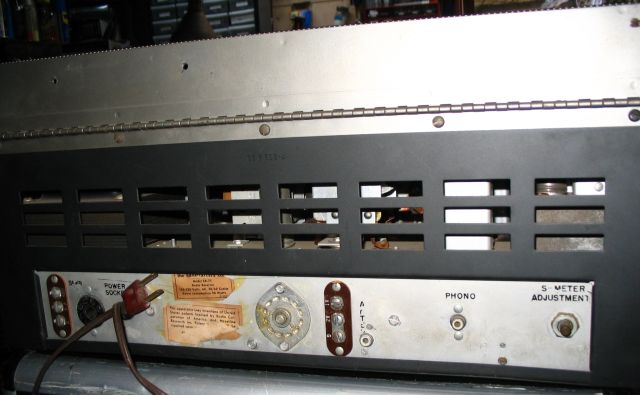
There seemed to have been a fuse and fuse holder added (bottom left in the photo above). This was cracked and broken. I removed it completely, and replaced it with a new fuse holder in the live half of the incoming power cord. I added a grommet to the entry hole for the power cord, and tied a small knot in the cord just on the inside of the hole.
Two of the knobs were non-Hallicrafters. The CW Pitch knob
(already mentioned), and the Sensitivity knob. Also, the Volume control knob had
been damaged in shipping (shown here sitting in front of the receiver)
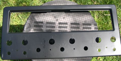
The bottom left hand side of the front panel was dented. This impact was probably the cause of the bent CW pitch control shaft. Here are closeup pictures of the front panel.

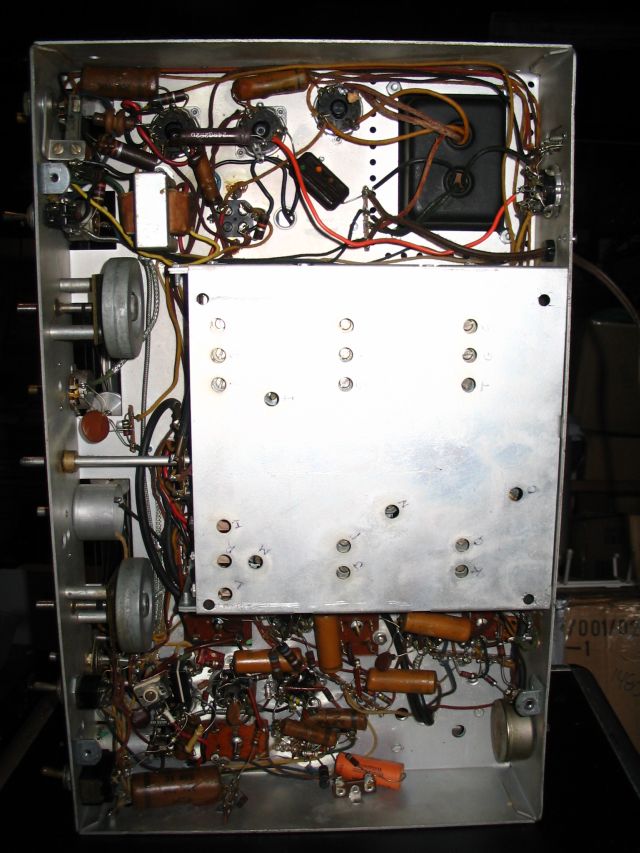
The underside of the chassis revealed some capacitors had been replaced. This is a fairly standard procedure advocated by restorers of old radios. I have my doubts whether it is a good idea unless the capacitors in question are really shown to be bad.


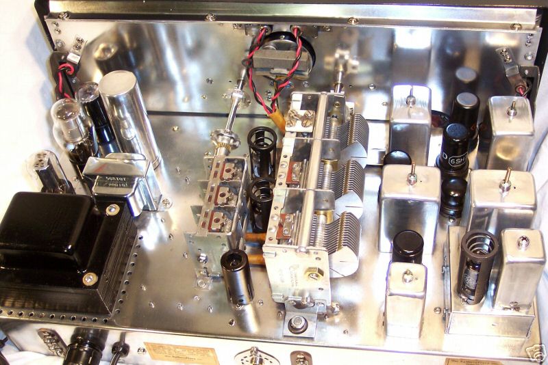
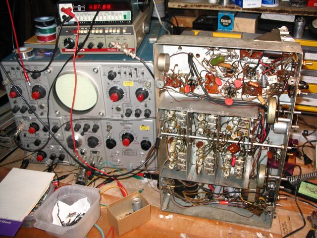
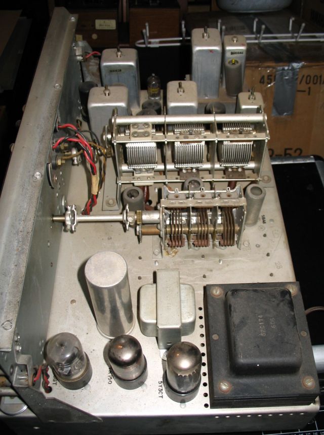
The upper side of the chassis looked dusty and slightly rusty. Most of the tubes looked like they'd been replaced at some point in the recent past. None of the tubes were Hallicrafters originals.

The top left canned inductor coil in the above photo appears to be missing it's core, but in fact is not: all SX-71s look like this :-)
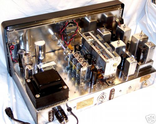
Here is a photo of the SX-71 with all panels, dials etc. removed.

I stripped the paint off the cabinet, rubbed it down with a fine emery cloth and spray painted it with "Plasti-kote" Black 637 car spray from Pep Boys - a near perfect match for the original Hallicrafters colour. For the top lid I spray painted with silver car spray.
I removed the front panel, beat out the dent as best I could, then covered all the control lettering with small pieces of sticky tape. I then prepared the surface for painting, and sprayed it with the 637 spray. Here is what it looked like after doing that:
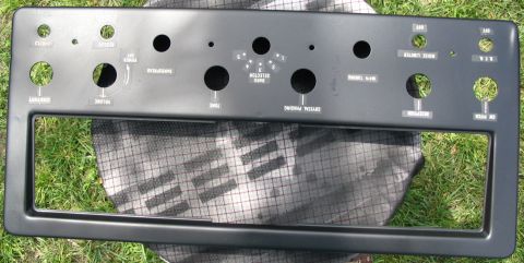
Then I removed carefully the small pieces of tape, and applied a polyurethane clear finish. This gave the whole panel a dull shine, which is quite attractive. Of course the areas where the tape was applied around the lettering is noticeable if you look closely. The alternative was to leave the panel unrestored, or try to duplicate the lettering after a complete repaint, which I knew would be extremely difficult (see the story about the SX-110 dial scale below!). The picture below shows the panel after removing the tape, and before the polyurethane finish was applied.
Finally, to complete the front panel, I replaced the two window pieces of perspex with two freshly cut pieces of clear glass, using weatherstrip down the edges so that I could tighten the glass clamps without fear of breaking the glass.
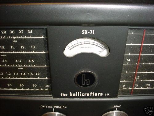
Here is a photo of the dial, for completeness. Click on the photo for a larger version.

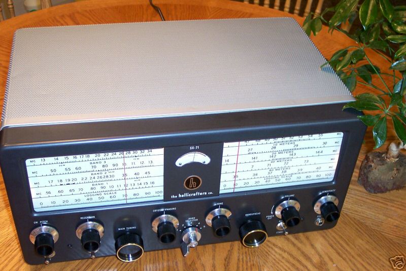
Here are some pictures of the finished cabinet work.
Electronics
I then set up the SX-71 on the bench, ready for electrical tests.
I removed the cover of the HF coil circuits. It had some spots of nasty rust on the underside, which I cleaned up with Naval Jelly.
Checking around the circuit, I found that R35 (3.3k) looked charred. It measured only 100 Ohms, so I replaced it.
I couldn't understand why the regulated voltage on the VR150 was 110V instead of 150V, until I looked closely at the tube: it was an 0C3 and not a 0D3! I.e. it was the wrong tube. I replaced this it with a true VR150.
Hallicrafters SX-71 (Number 2 - Run 4)
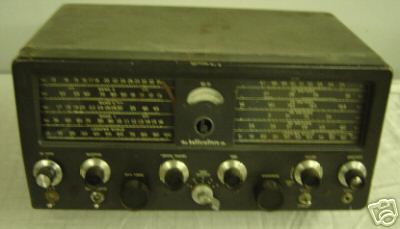
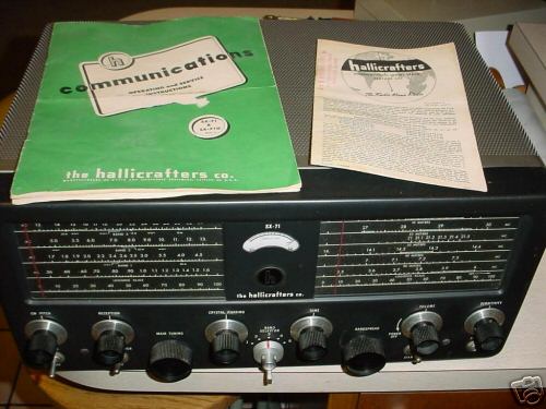
An $80 purchase on Ebay (picture shows the unit as it arrived, with knobs removed for inspection of front panel condition). Came with an outboard tube-based 100kHz crystal calibration oscillator, which had been attached to the rear of the hinged lid. Also came with complete original owner's manual, plus instructions and circuit for crystal calibrator. Power socket rewired to supply crystal oscillator. Missing CW Pitch knob, Tone, Volume and Sensitivity knobs not original. BFO switch bent.
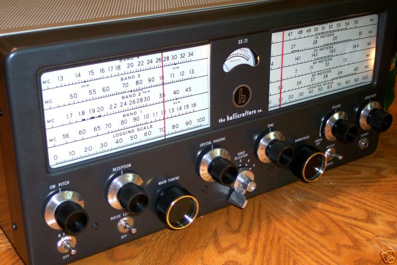
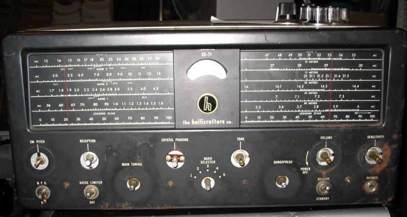
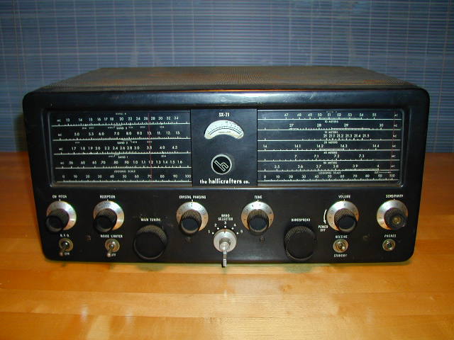
Overall, the condition of this second SX-71 was better than my first one. Notice the marked difference between the Run 3 (top) and Run 4 dial markings:

In particular, Run 4 SX-71s have the 15 metre band (an extra band) marked on the bandspread (right) half of the dial. WWV frequencies are marked on the main tuning scales, and the font size is smaller. See below for other known SX-71 Run number differences.
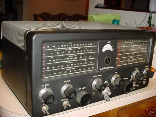
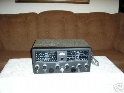
Here is the completed Run 4 SX71, after cabinet refinishing, cleaning and alignment:

Here's a view with the top down:

Close ups of the illuminated dials (click images):


Here is a photo of the finished Run 3 and Run 4 units sitting one above the other.

Setting the CW Pitch Control (BFO)
Here is advice from Rodney Bunt on setting the CW Pitch Control position correctly:
To get the '0' position, for the BFO.

This is how you get it right by "ear"

One assumes that you have done an alignment. And that you know the
frequency of the last IF (this should be that which the crystal
filter passes in the narrowest setting).

Inject an IF signal (carrier only) at the output of the second mixer
V4 pin 4. Turn on the BFO, and listen to the speaker output, adjust
the screw in, or out, so that the sound in the speaker goes
"shwoosh" IE: It starts at a "higher" pitch and the "noise" gets
lower in tone, until it starts to get higher in tone again. rock the
BFO back and forth through this "shwoosh" the point with the lowest
tone IS the 0 position, put on the knob with the 0 uppermost. Knob
is 0-5-0 type knob.

(Elaboration on the above advice...)

1. If you inject a signal then you should set the BFO
shaft for a "ZERO beat".

2. The "by ear method" uses the "receiver noise" that is alway present
in any receiver, and using the  narrowest bandpass of the XTAL filter,
you tune the BFO to ZERO position using the "Swoosh" method, not by
injecting a signal.
SX-71: Differences between the Run Numbers
The following information has been picked up from various sources, or inferred from circumstantial evidence. If you see an error, please contact me: julian.bunn@caltech.edu
Run 1: White face dial (see pictures at the bottom of this web page) i.e. black lettering on white background. Bandspread and Main Tuning knobs have metal ring inserts. Bandspread dial does not show 15 meters.
Run 2: Tuning knobs have metal ring inserts. Bandspread dial does not show 15 meters.
Run 3: Tuning knobs have no metal ring inserts. Bandspread dial does not show 15 meters.
Run 4: Tuning knobs have no metal ring inserts. Bandspread dial shows 15 meters.
Comment about Bandspread/Main Tuning knobs: some SX71s have metal rings inserts in these knobs. The metal rings are apparently silver-plated brass. (Sometimes the silver coating rubs off, so exposing the brass.) These knobs appear similar to the knobs on the S40A, except those do not have silver plating.
Jim Cain's SX-71
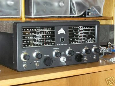
Jim Cain kindly lent me his SX-71 while I refurbished mine. This is very useful, because a direct comparison is possible for e.g. the CW Pitch control and knob. Here is a photo of the front of Jim's receiver:

(The CW Pitch knob was temporarily removed in this photo.)
Informational links for SX-71 receivers:
Specifications:
http://www.dxing.com/rx/sx71.htm
http://portabletubes.co.uk/boats/hsx71.htm
Restoration Projects:
http://www.w9wze.org/df.php?dn=Restorations/SX71.wp
http://www.amfone.net/SX71restor.htm
Parts etc.
Gary Brown's site: http://tubes_tubes_tubes.tripod.com/
For sale/wanted
Help on restoration
More parts
Knobs: http://www.oselectronics.com/ose_p101.htm
Knobs: http://www.unicornelex.com/newunicorn/subcategory.php?cat=E11E28&
Knobs: http://www.marvac.com/SearchResult.aspx?KeyWords=knob
Knobs: http://www.farnsworthelectronics.com/knobs.htm
Alignment & Service:
ftp://bama.edebris.com/bama/hallicra/sx71/sx71align.pdf
Service Bulletin #1950-109 (courtesy Rodney Bunt)
Alignment Page 1, Page 2, Page3
Here's an interesting discussion on Alignment of the SX-71 in Google News: Crystal Filter Alignment
Modifications and Circuit Analysis:
"Soup up your SX-71" (By Phil Atchley, sent to me by Rodney Bunt)
A redraw of the SX-71 IF from Chuck McGregor, who comments "Unlike the SX-42 and SX-62 which run the first IF at fixed gain using a 270 ohm cathode resistor to ground, the SX-71 returns both the first and second IF cathodes to the wiper of the sensitivity control, through different resistances and changes those resistances for the second IF on a band-by-band basis. It would be great to find an explanation of WHY, from the guy who designed it.... "
Manuals and Sams Photofact:
http://bama.edebris.com/manuals/hallicra/sx71 (Run Number 3, 1950) or locally.
http://bama.edebris.com/manuals/hallicra/sx71sams or locally.
This is a scanned full colour copy of my original Hallicrafter's SX-71 Run 4 manual. The previous owner has made annotations on some of the pages.
General interest:
http://hug-a-bug.com/SX-71.html
http://www.usenet.com/newsgroups/rec.antiques.radio+phono/msg17055.html
http://antiqueradios.com/forums/Forum16/HTML/000093.html
Manual reprints:
http://www.radioreprints.com/descriptions/sx71.htm
Photos:
http://www.qsl.net/la5ki/sx71.htm
http://users3.ev1.net/~wck5/radpix/halcrft/SX71.jpg
http://www.w9wrl.com/w9wrl/sx71.jpg
http://www.rigpix.com/hallicrafter/sx71.jpg
http://www.oldradios.co.nz/gallery/anchors/HALLICRAFTERS%20SX-71.jpg
Other Hallicrafters Information
SX series Hallicrafters Receivers
More SX series Hallicrafters
http://www.dxing.com/rx/sx99.htm
http://www.obairlann.net/~reaper/ham/sx-110/
The Hallicrafters Web Site: http://www.w9wze.org/
Some photos of SX71s picked up around the Web
(Let me know if any of these are yours, and I will be glad to add an appropriate caption).
Here are some pictures of a recent (June 2005) auction for a superbly restored white face SX71, by Wayne "hallicraftersguy" on Ebay: