The Minisonic2 Analogue Sound Synthesizer
Introduction
G.D.Shaw's Minisonic 2 synthesizer appeared as a construction article in "Sound Design" in the 70's. It was based on his Practical Electronics "Minisonic" which appeared in PE Magazine in 1974. The Minisonic in turn was based on the "PE Sound Synthesizer" that first appeared in PE Magazine in February 1973.
The Minisonic 2 features:
1) Two Log Law Temperature compensated VCOs with vernier tuning
2) Oscillator Phase Locking up to 9th harmonic
2) Two Envelope Shapers
3) Stereo output with panning
4) External inputs
5) Voltage Controlled Filter (3Hz-15kHz)
6) Two Octave Keyboard
7) Toggle Switch patching (23 switches)
8) Variable Portamento, glide effects up to 1s
9) Ring Modulator
10) Noise Generator
Here are photos of the three synths:

Here is a more detailed image of the Minisonic2 (click for a full size version):

At the bottom of this web page you can also see some photos of Steve Thomas's original Minisonic2.
Nov 2009: images of Minisonic Serial Number 1 have been added at the end.
February 2016: Here is a photo of Phineas Ramsay's Minisonic 2 (an early prototype from Eaton Audio):

As a boy, I always wanted to build one of these synths, but could never afford the components. Well, now I can, so I recently decided to attempt the construction of the Minisonic2. I am very fortunate to be in touch with Doug Shaw himself, who has kindly sent me an original Minisonic2 printed circuit board, an original copy of "Sound Design" and several hard-to-find semiconductors (more on those below). Doug Shaw has an interesting web site now up.
This document will be used to detail progress in the project. It may even be useful for some intrepid individual who decides to build one of these lovely instruments in the future!
Some Useful Information On Synthesizer Building
The Cloned Analogue Gear website has a lot of scanned articles and photos related to analogue synthesizers of yesteryear, including the Minisonic2 and the PE Sound Synthesizer.
There is an excellent email list for people building synthesizers, run by Rick Jansen called Synth-Diy. This email list is archived, and the archive can be searched using this page.
The design for the Minisonic2 is detailed in the PE book called "Sound Design", a copy of which Doug sent me. The following link will take you to a PDF file of the complete article, scanned. This is a 12MB download, so beware! Sound Design - Minisonic2.
Yves Usson has an excellent site with a lot of material related to synthesizers of yesteryear.
You can buy synthesizer keyboards at http://www.doepfer.de/preise.htm#Keyboards .
Ken Stone's Sequencer: http://www.cgs.synth.net/modules/gate_sequencer2.html
Various filters etc.: http://www.experimentalistsanonymous.com/diy/Schematics/Filters%20Wahs%20and%20VCFs/
The Completed Instrument
Here are some sound samples I recorded from the Minisonic2, to try to cover some of the basic possibilities. They aren't Mozart :-)
- 01 - VCF.mp3 (250kB)
- 02 - Noise Generator.mp3 (480kB)
- 03 - Ring Modulator.mp3 (670kB)
- 04 - Cross Mod VCO.mp3 (1170kB)
- 05 - VCO Sync Filter.mp3 (2340kB)
- 06 - Noise Filter.mp3 (1610kB)
- 07 - Noise Ring VCO.mp3 (470kB)
- 08 - Various.mp3 (1190kB)
You can see a short YouTube video of some initial tests of the Minisonic at http://www.youtube.com/watch?v=AG5ba0awHu0
Here are some images of the completed instrument. The following sections detail its construction.


Collecting the Components
The Minisonic2 design is based around 741 op-amps, which are still readily available, but it also uses several obsolete or hard to find semiconductors:
- MFC4000B (250 mW output amplifier) [Available from www.squitter.com ]
- SG3402N (four quadrant multiplier) [From Doug, also available from www.jmb-electronique.com ]
- MFC6040 (electronic attenuator) [One from Doug.I bought 5 from www.organservice.com . Also available at www.squitter.com, www.ges-electronicpool.de ]
- MD8001 (dual transistor for temperature stabilization circuits) [From Doug]
- Z5J (noise diode) [From Doug. Impossible to find anywhere?]
- LM709 (op amp) [Surprisingly hard to find. I found two from old stock dated 1999 at Marvac www.marvac.com in Pasadena]
Fortunately the rest of the components are easy to obtain, and I ordered most from www.mouser.com (I already had a few in my component drawers).
Keyboard
I couldn't find a plain simple 36 key keyboard in any of the online components catalogues I searched in. Nor did a Google search throw up any useful sources. In the end I decided to buy a very cheap, simple electronic organ with 37-key keyboard that was going for 0.1 cents on Ebay (I ended up paying $2.15 for it, plus shipping of about $20). My hope was that I could extract the keyboard and discard the rest. Here is what I bought:
When it arrived, I couldn't resist plugging it in and hearing what it sounded like. I quickly unplugged it: I have rarely heard a more unpleasant electronic noise. Opening it up, I found that I could extract the keyboard assembly, which happily used a resistor chain and was thus perfect for the Minisonic2 (which requires a chain of 36 47Ω resistors):
 (Showing
the innards of the cheap keyboard.)
(Showing
the innards of the cheap keyboard.)
After extracting the keyboard, I mounted it temporarily using a few pieces of beading and offcuts:
The way the keyboard works is as follows: underneath each key is a small flexible metal tongue that gets pushed down when the key is pressed. All the metal tongues are connected together by a strip of metal. When the tongue gets pushed down, it touches against a junction in the resistor chain. Thus a connection is made between the metal strip, the tongue, the junction in the resistor chain, and then all the resistors that are in the chain between the junction and the end of the chain. So an ohmmeter connected between the metal strip and the end of the resistor chain sees a resistance that varies linearly with the position of the pressed key.
The linear relationship only holds if all the resistors in the chain are the same value. Of course they are not precisely the same, especially if using standard 5% tolerance components. The Minisonic2 article gives guidelines about how to deal with this situation (involving placing like-valued resistors at the same position in each octave). Accordingly I sorted out my 47Ω resistors into seven groups:

(Notice how only two resistors are within 0.5Ω of the nominal value, the rest are all greater in value!) Once sorted, I simply positioned them in the chain, soldered them in position, and then snipped away the resistors that came with the keyboard.
Now the prototype keyboard was ready for use in testing the Minisonic2 as each of its electronic sections was completed.
Voltage Controlled Oscillators
The two voltage controlled oscillators are controlled by a pair of transistor "ovens". The ovens are included in circuits called "VCO comparators" in the design. The ovens produce a current source that is temperature stabilised and whose value doubles for every 0.5 Volt increase on the comparator input. A precision ten-turn potentiometer is used to precisely adjust the input voltage, and thence the current being sent from the oven to the VCO (and thus the frequency of the VCO).
The first obstacle I met was having to find a replacement for the MD8001 dual transistor IC, of which I only had one. Use of the MD8001 guarantees close thermal coupling between the transistors, and the device has particular linearity characteristics that make it desirable over e.g. the CA3046. A sub-optimal alternative is to glue together a pair of suitable transistors, and bind them with wire to try to get good conductivity between them. Initially, however, I tried a supposed "equivalent" to the MD8001, the MD708B, but this proved to be useless. I then glued and wire-bound together a pair of BC338s and used those.
The setting up of the ovens is a bit of a fiddle, but I was able get very good current scaling with minimal adjustment of the presets, on both the comparators.
Once the comparators were completed, I assembled the two VCOs, and attached the ccg (current source) from each comparator to each VCO. I then hooked up the 'scope and saw very nice sawtooths from each VCO, whose frequency I could vary with the 10 turn pots.

The picture shows the board appearance at this stage. Here's a close-up of the two transistor ovens:

Here is a scope image showing the waveform from VCO1 (top trace) and VCO2:
I managed to match the VCOs and they seem to be working alright: using the vernier dials on the ten turn pots, I compared the frequencies of the sawtooths:
- min frequency on both is around 20Hz
- max frequency on both is around 15kHz
- if I use the scope and set both VCOs independently to a frequency of 1kHz precisely, and look at the vernier setting, both read exactly the same i.e. 4.8 (out of 10).
So it looks like the low/mid/high are matched.
However, the voltage measurements are a little different between the two. Recall that my VCO1 uses the MD8001 dual transistor, and VCO2 uses a glued pair of BC184.
With VR10 wiper at -6V, VCO2 current with R58 disconnected cannot be reduced by VR8 below about 50uA. VCO1 can be adjusted to 24uA.
Moistened finger on pair with R58 connected: I cannot stabilise VCO1 at any setting of VR11, the drift in the current is always upwards, but leisurely. On VCO2, there is negligible drift, and I didn't have to adjust VR11 at all (it remains at zero Ohms). This puzzled me, because I was expecting the glued BC184s to be more picky and difficult to set up than the MD8001.
For the final set up I adjusted the current to be 50uA in both VCOs, and then I adjusted VR9 and VR12/13 to match the frequencies at the limits and mid way. (VR9 adjustment isn't mentioned in the Sound Design article I don't think, but looks like it should be used to trim in this way.)
Ring Modulator
The Ring Modulator is based on the SG3402 IC. It was completed without any problems.
Voltage Controlled Filter
The VCF uses a constant current source to drive a diode/capacitor ladder network, whose tuned frequency varies according the current.
Here is the ladder network on the PCB:
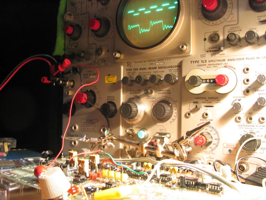
Here is a photo of the VCF under test with a square wave input (Tektronix 556 dual beam scope with 1L5 spectrum analyzer and L plug-in)
Noise Generator
The noise generator is based around a "noise" diode called the Z1J/Z5J from Semitron (a UK Company). Doug kindly sent me two, otherwise I would have been stuck, since I couldn't find anywhere that sold noise diodes, let alone this particular sort. Construction was easy, and the generator worked first time. The output is a random signal, White Noise. Here is a scope trace of the output from the generator:
Envelope Shapers

These caused me a lot of trouble, for some reason. For a start, TR4/5 obstinately refused to turn on and off as a function of the applied signal at the inputs. I was particularly bugged by the BC184 which was "off" with no triggering signal. Its emitter was slightly +ve, but only slightly.
Here is a table I made (with VR18/19 at zero Ohms) of the voltages at various points, as a function of applied voltage to pins F and A:
| Comment | Pin F | Point B (virtual Earth) | TR4/5base | TR4e | TR5e | TR5c | IC11pin6 |
| F,A unconnected | 0.55V | 0.0V | 0.53V | 0.06V | 0.0V | 3.35V | -0.6V |
| B grounded | 0.55V | 0.0V | 0.53V | 0.07V | 0.01V | -3.09V | -0.8V |
| "Hold" | -5.33V | 0.0V | -5.32V | 0.00V | 0.0V | -4.92V | -0.3V |
| PinF @ -9V | -9.00V | 0.0V | 8.60V | -0.47V | 0.0V | -4.92V | 4.5V |
I could make TR4 turn "on" (i.e. make its emitter rise to +9V) by applying a +9V wire to its base. Normally the base is at +0.53V, with no applied signal, and this was insufficient to turn TR4 on. This voltage is set by R91 and R90, and should be 9V*3.9k/(75k+3.9k) = 0.44V (not sure why it is higher than that, maybe emitter leakage current?).
I made the observation that both the Envelope Shapers have the same voltage distributions as in the table above (to within a few tenths of a Volt), so this argues against a wiring problem. Something more fundamental is wrong.
I tried various other npn transistors in place of TR4, noting that some were better than others, until in the end I found some BF255 high frequency amplifier types, which seemed to do the right thing. The next problem was that the attack/decay rates were far too long ... several seconds when the attack/decay pots were at minimum value.
In the end I decided to simulate the first couple of stages using Linear Technologies LTSpice program, a free download. Here is the simulation, which produced exactly the expected behaviour of the output of the opamp, and NOT the behaviour I was seeing.

The interesting aspect is the voltage source V1 � this is set up to produce a -9V pulse after twenty seconds, hold it for 5 seconds, and then revert to ground. This is as if the user presses a key on the keyboard for 5 seconds.
The upper diagram shows in green the voltage at the base of (Minisonic) TR4/5 � about 0.6V dropping to -3.2V when V1 pulse appears, and in red the output of the opamp. Note the rise and fall time of the envelope is lengthy: the same circuit with R6/R7 each a nominal 1Ohm shows an almost instntaneous rise and fall time.
Update (May 2004): the reason for my problems with the Envelope Shaper front end is found: I had inserted the BC214 transistors assuming that their pinouts were the same as the BC184. They are not! Once I re-orientated the BC214s, everything worked fine.
Here's a picture of the MFC6040 attenuator IC (hard to come by):

Keyboard Controller and Hold
I was tinkering with the Hold circuit and can adjust VR7 so that there is very little drift indeed. I notice that, with the best setting, the voltage goes +ve very slowly, then goes -ve very slowly, turns around and goes back ... and so on. The period of this oscillation is about 30seconds. It seems that every time I turn the instrument back on after it's cooled down, then I have to wait for the hold circuit to settle.
In Fig1 I am puzzled about the use of VR6 ... I set the wiper to midway and do not seem to need to alter it.
Also in IC1 and IC2 ... I'm not quite sure how to do this. So I set it up as follows: with identical voltages on pin2 for both ICs, I adjusted IC1's output using VR4 to be the same as IC2's output.
I have a problem with the Tune control, VR5. It doesn't seem to affect any of the voltages at IC1&2 pin 2. Yet point CC is certainly swinging between 0V and +5V. I must have something disconnected, since when written down this doesn't seem possible.
Hold Isolator
A subtlety here is that the PCB doesn't contain places for IC10 and related components: they are to be mounted on the PSU PCB, which I do not have. Thus I needed to do something special. Moreover, I was advised by Doug that the HF triggering system was sub-optimal and that an alternative should be sought based on FET opamps.
Here's a closeup of the HF Oscillator section on the PCB:

I have two TL071 FET opamps I'm experimenting with using for the hold isolator. Initial tests are encouraging, using a follower configuration. In fact I notice that Fig2 in the Sound Design article already describes a suitable very high input impedance follower circuit that I can maybe use for the Hold Isolator (see below).
This investigation is still underway. Right now (May2004) I am using the HF oscillator system, and no hold isolator (i.e. no relay in circuit) with acceptable results. For completeness, here is the method of connecting the HF detector into the Envelope Shapers ...
Panel Design
The Minisonic2 design calls for a set of DPDT pushbutton switches that control the signal routing between the modules. I was surprised at how hard it was to find reasonably priced DPDT pushbutton switches. In the end I ordered some rather large DPDT rocker switches. I realised that the panel design for the Minisonic2 was not going to work with these switches (they are too large), so I set about repositioning all the controls on a 24"x12" panel, using PowerPoint. This is the design I came up with:
I really wanted a temporary panel which I could mount the switches and pots on, and wire up, just for testing before installing in the final box (which I had yet to make). So I printed the panel design onto thick paper (using a large HP DesignJet printer), and then took a piece of foam core and spray-glued the printed paper onto it. I then trimmed the panel to size:

At this point I realised that I really didn't want to use the large DPDT switches, and instead purchased a set of DPDT toggle switches. I then mounted all the pots, switches and knobs onto the prototype panel:

You will notice that I am still missing a couple of pots (in ES2 and Pan2). The foam core is sufficiently rigid that it easily holds the weight of all these components.
A friend recommended a place I could get a panel made to my specifications, lettered and drilled, as a one-off job. I accordingly contacted BNP Lasers who were extremely helpful in suggesting suitable materials and engraving possibilities. They sent me some small samples of etched and back painted plastic, and a piece with various diameter cut holes, essential to get an idea of what the finished product would look like and how it would work. I settled on 1/4" black plastic for the panel, with white lettering. Before placing my order I needed to make some very careful checks on the exact dimensions of the required holes, and make some modifications to the PowerPoint design file to take into account:
- the Vernier dials which I decided to use for the VCO frequency controls,
- a few extra bolt holes for fixing the panel to the piano hinge at the rear,
- holes for LEDs on each Envelope Shaper that indicate triggering
- the reduced size of all the switches on the board (now the miniature DPDT).
Output Stages
The output stages were completed without any difficulty. The output for the headphones/speaker is generated by an MFC4000B 250mW audio amplifier IC. A separate output is generated by a 741 op-amp. Here is the op-amp output for a 3kHz square wave input (top trace): (Same volts/div setting for both traces)
And here is the MFC4000B output for the same input:
Cabling Up the Panel
Using the foam-core mock up of the panel, I attached all the switches and potentiometers, and then began the task of wiring up the circuit board to the panel. This turned out to be very time consuming indeed. I used 16-wire flat cable, in an effort to reduce the grandmother's knitting effect, but the switching circuitry and just the sheer number of panel components in the Minisonic2 makes for a very involved wiring task, and I found it hard to keep it neat. Here is a picture of the completed circuit board partially cabled to the panel:

Once this task is done, then it should be a simple matter(!) to remove the pots and switches from the mock-up panel, and re-insert them into the final plastic panel.
Making the Cabinet
I drew up a design for a simple cabinet that would hold the control panel at an angle, the circuitry inside, and the keyboard at the front. I constructed the cabinet from veneered 1/4" plywood, using 11/16" square rod to strengthen the edges. Here is a picture of the cabinet almost completed, before adding the hinged control panel and fixing in the keyboard assembly (anticipated to be the most complex part of the job):
Doug's Minisonic2 VCF 'scope traces
Doug Shaw sent the following images from measurements made on a Minisonic2 with a waveform shaper tacked on to one of the VCOs. Click on each image for the full size version. Doug's notes are below each image.
 Range 'C'. Sweep 1Khz - 100Khz. Input signal 150mV p-p triangle. Resonant frequency 37Khz. Intermediate 'Q'. Output 100mV/div. |
 Range 'A'. Sweep 0.5Hz - 300Hz. Input signal 150mV p-p triangle. Centre frequency 27.5Hz. Low 'Q'. Output 100mV/div. |
 Range 'C'. Sweep 1Khz - 100Khz. Input signal 150mV p-p triangle. Mid-range resonant frequency. High 'Q'. Note interference pattern and peaks caused by changing harmonic relationships at different points of resonance. The sound is marvellous. Output 100mV/div. |
 Range 'B'. Sweep 10Hz - 1Khz. Input signal 50 mV p-p sine. Centre frequency 100Hz. Low 'Q'. Roll-off 3dB - 1st Octave; 6dB - 2nd & subsequent. Output 50mV/div. |
Steve Thomas's Minisonic2


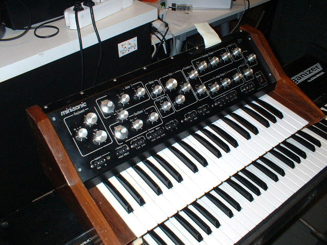
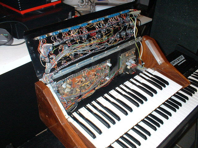
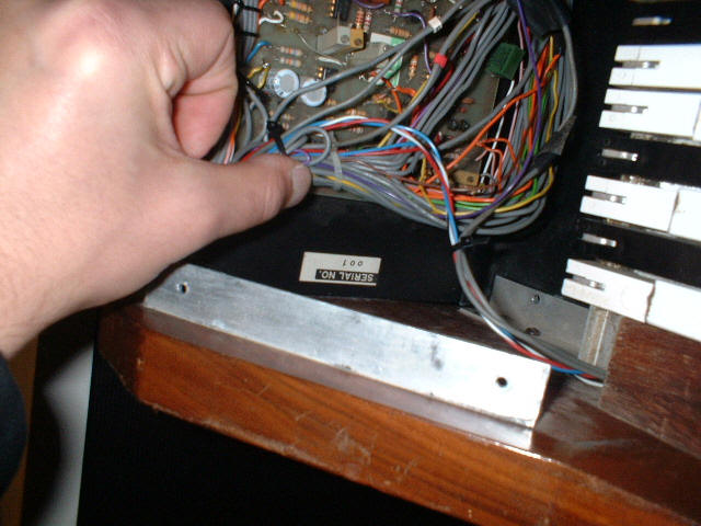
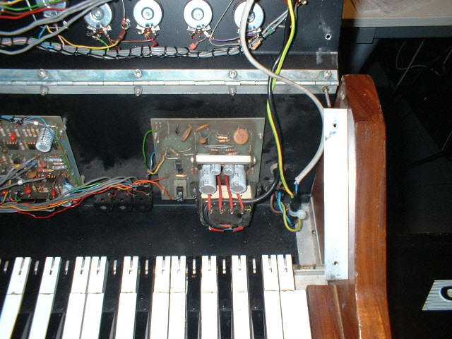
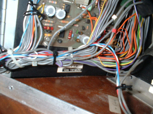
Minisonic Serial Number 1
These photos are courtesy of Federico at http://stillnovo.com/ which sells, repairs and renews old synthesizers, amps and guitars.