Hallicrafters SX-28 Serial Number H164061
I bought this SX-28 from Deane Kidd, who bought it in the 1970s.

The Serial Number suggests it was made sometime towards the end of 1942. On the chassis base plate is marked "Sold, March 21, 1964". Here is the SX-28, as received.
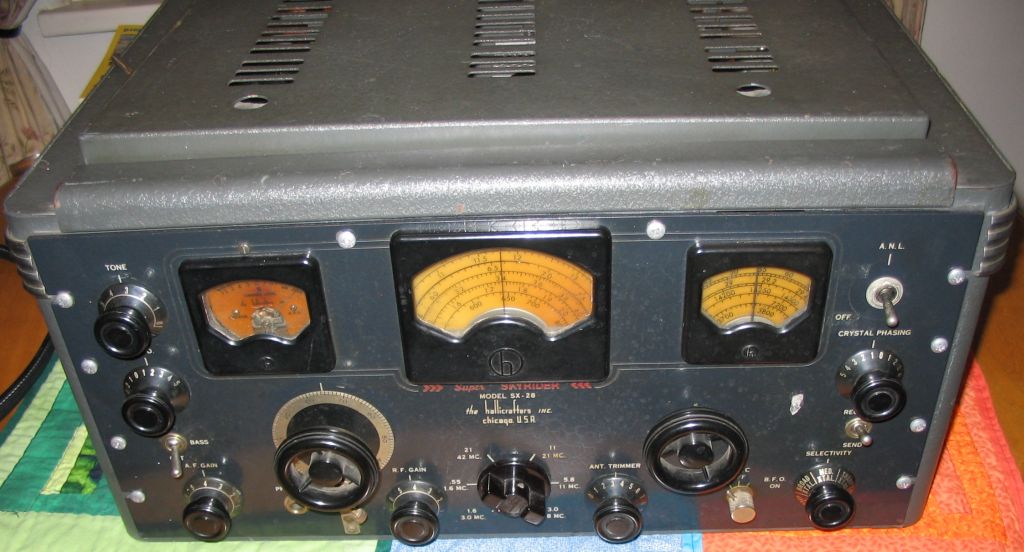
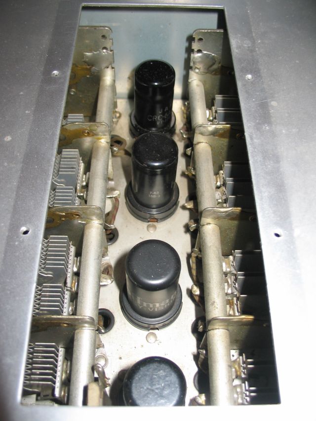
Notice that the ANL control has been replaced by a toggle switch. This was done prior to Deane Kidd's ownership. Behind the faceplate the switch is connected to a small metal box containing a tube and other components. This is perhaps a mobile ANL unit made by Gonset. The first thing I did was to replace this with the original circuitry, and add new pot/switch/knob for the ANL.
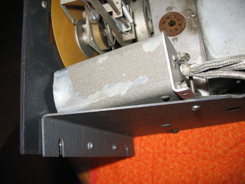
Interior, above chassis with the gonset unit

With the ANL pot and circuit replaced (top left hand corner)
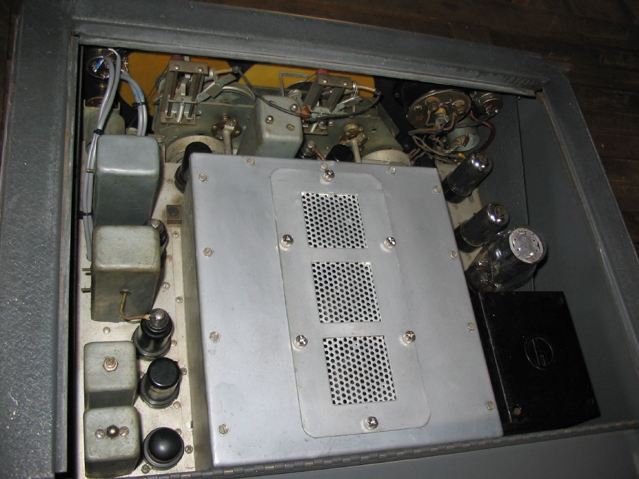
(Notice the screws for the RF box cover: these are modern PC parts)
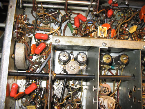
Under the chassis before component replacement began:

All the tubes in the set looked new. For example, in the RF section:
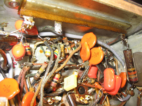
Recapping, Reresistoring
Some photos of the recapping. Many high value resistors were replaced subsequently.


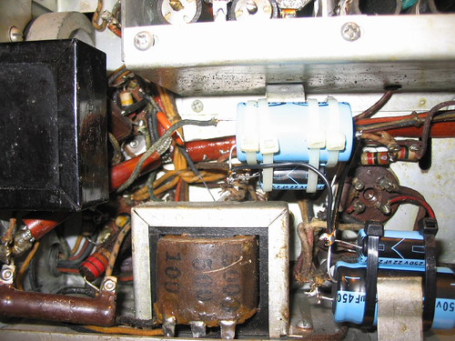

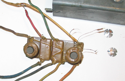
T2 IF Transformer
While recapping the IF and Audio stages, I noticed that a wire to the T2 IF transformer had been snipped at some point in the past. Various people suggested thiswas an accident, rather than a deliberate modification. Chuck McGregor drew the following schematic, showing where the cut was, and pointing out:
"In trying to figure out Hallicrafters poor schematics with their complicated multi-position switching, I have found it useful to redraw the circuit for each position of the rotary switch, leaving out any components that are open circuited in that position, and replacing shorted components with wire links. Example for switch position 1 is attached. When you do that, it's immediately obvious that C33 is the IF-frequency ground return for the secondary of T2...... and the V6 grid circuit, thru T2 secondary, is open circuited (for IF) with that link cut. So, any signal at all that makes it thru is due to stray capacitances, and the performance oughta be lousy."Here's the schematic section involved.
The IF transformer itself was not in a good state: one of the adjustment lugs was immovable. I had to disassemble it and rewire it inside:
Documentation
- SX28A AN/GRR-2 (Military designation) Manual - 78 pages (PDF)
- SX28A Manual (DJVU)
- SX28A Manual Front Pages (TIF)
- SX28A Operation Description Maintenance (TIF)
- SX28A Parts List (TIF)
- SX28A Schematic in A3 format (TIF)
- SX28A Schematic in A4 format (TIF)
- SX28A Military Manual (DJVU - 35 pages - equivalent to TIF versions)
- SX28 Military Manual Part 1 (DJVU)
- SX28 Military Manual Part 2 (DJVU)
- SX28 Schematic Annotated with component values by KH6GRT - Page 1 (DJVU)
- SX28 Schematic Annotated with component values by KH6GRT - Page 2 (DJVU)
- SX28 Schematic Annotated with component values by KH6GRT - Page 3 (DJVU)
- SX28 Schematic Annotated, as above (PDF)
- SX28 Service Bulletin 1951-30, August 6, 1951 (PDF)
- SX28 Manual 1941 (07292840) High Quality (PDF)
- SX28 Alignment Procedure by Bill Feldman N6PY (PDF)
Band Indicator Stringing Diagram
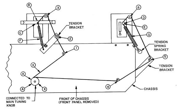
(courtesy of Doug Moore)
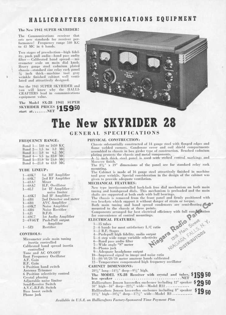
Adverts